This topic provides network designers and administrators an overview of the requirements needed to implement a Q-SYS audio distribution system on a converged network. In order to simplify this group of networking requirements, and for ease of communication between parties, QSC has named these requirements the “Q-LAN Protocol Suite". For more information about the Q-LAN Network, refer to the Q-LAN white paper.
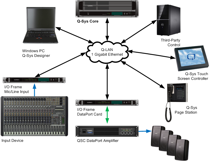
Q-SYS is a system that performs complex routing, processing and management of audio in a facility. The elements of a Q-SYS system include:
All Q-SYS network protocols are Internet Protocol (IP) based and support advanced networks beyond the simple Ethernet Local Area Network (LAN). Because Q-SYS is a system for live audio, real-time performance is required on both the LAN and the IP environments. In an IP network, routers replace some, or all, of the network switches. Therefore, routers need to provide the same level of performance as the switches they replace.
NOTE: In Q-SYS Designer, you can use the Core’s Network Receive Buffer setting to relax network real-time performance requirements at the expense of increased audio latency through the network.
Layer-3 IP networks have advantages in manageability, scalability, security and convergence over their LAN counterparts. If yours is a large, critical and shared network, it is likely your application will benefit greatly from layer-3 networking.
Layer-3 networks handle QoS and multicast routing in a more engineered manner.
Audio is transmitted in streams. A stream is an ongoing series of packets. Each packet contains 16 audio samples for each of up to 16 audio channels. Samples are in 32-bit floating point format. The maximum total payload size, including overhead, for an audio stream packet is therefore 1100 bytes (octets).
A Q-SYS Core may generate and receive up to 128 audio streams. An I/O Frame or Page Station receives and transmits a single stream.
All streams for a system operate synchronously at the same sample rate. The only sample rate currently supported is 48 kHz. In the future, QSC may add other sample rate and data format options to the protocol.
Hardware found in a Q-SYS System, requiring a connection to the Q-LAN network, includes:
You can configure your PC-based Q-SYS Designer or UCI Viewer, and Apple iPad/iPhone to discover and connect to a remotely located Core. The device must have network connectivity with the Core(s) to which you wish to gain remote access. This can be via VPN or some other method suggested by your friendly network administrator.
A Hard Link is the IP Address of the Core to which you wish to connect. You may include multiple IP Addresses.
The PC running Q-SYS Designer or the Q-SYS UCI viewer needs to be able to reach the following ports on the target Core:
In addition, the PC must be able to exchange ICMP (ping) echo messages with the Core. There are separate firewall settings to enable or filter these messages. You can test network connectivity by pinging the Core(s) from your PC using the Windows command line interface (cmd.exe) and the Core's IP Address. The format is ping 123.45.6.789. If you get a good response, (for example: "Reply from 123.45.6.789: bytes=32 time<1ms TTL=64) you have the proper connectivity.
IMPORTANT: Do not use this method if your UCI device can already discover the UCI's on the Core, that is, receive multicast packets from the Core in question.
 button at the bottom of the dialog box. The Edit Hard Link dialog box displays; the IP Address is all zeros.
 button at the bottom of the dialog box. The Hard Link is deleted.
The Q-SYS Q-LAN network communicates control information, streaming audio, and synchronization for a Q-SYS audio system.
The Q-SYS Q-LAN network uses the following standards:
NOTE: Q-SYS versions prior to 3.0 used UDP ports 6511 through 6766 as needed, depending on the number of active streams in the system.
Quality of service (QoS) allows different traffic streams to receive different treatment on the network depending on their stated relative priorities. QoS is required in the Q-LAN network to prevent non-real-time control and bulk communications from affecting performance of time-sensitive clock and audio-stream traffic. Network performance analysis and specifications are predicated on a QoS mechanism to differentiate and, to a great extent, isolate the different types of traffic on the network.
QoS ensures timely delivery of network data including audio. The Q-LAN network must be configured to prioritize traffic according to Q-SYS QoS classifications.
Q-SYS uses the DSCP field in the IP header to specify traffic priority to the network. The network must inspect, distinguish, and prioritize the following three traffic classes.
| Q-SYS Priority | DSCP Assignment | Traffic Type |
|---|---|---|
|
Highest |
46 (101110) - Expedited forwarding (RFC 3246) |
Clock distribution |
|
High middle |
34 (100010) - Highest priority (AF41) Assured forwarding (see RFC 2597) |
Audio streams |
|
Lowest |
0 (000000) - Default (best effort) per-hop behavior (RFC 2474) |
Control and management traffic (everything else) |
Network administrators may choose to trust the DSCP values transmitted by Q-SYS or alternatively reassign new DSCP values based on these values or other distinguishing traffic characteristics. As long as traffic is properly prioritized, it is not necessary to preserve these exact DSCP values through the network.
Flow control protocols (principally 802.3x) are used to prevent input buffer overflows. Modern switches have adequate internal bandwidth such that input buffer overflow is not typically a concern. 802.3x flow control is considered by many network vendors to be a relic. Switches with bandwidth meeting or exceeding wire speed should never have occasion to initiate flow control. The assumption is that the Q-SYS wire-speed requirement implies that switches in a Q-SYS network will never invoke flow control.
Network performance criteria for Q-LAN require no jumbo packet through all audio paths on the network. The presence of jumbo packets on Q-LAN-shared network links, even if on a separate VLAN, introduces additional network latencies making a single switch hop produce the same delay and delay variation as 6 switch hops with standard framing.
Jumbo packets will only be present on a network if network equipment is configured to pass them and end stations are configured to generate them. Fortunately, managed switches typically ship with jumbo-packet support disabled by factory default. End stations such as routers and servers also generally ship with jumbo packets disabled. A concerted and systematic configuration effort is required to enable jumbo packets on a network.
Q-SYS uses IEEE 1588-2002 Precision Time Protocol (PTP) for distribution of audio sample clock. PTP uses:
PTP transmits using IP multicast addresses
The actual address used for a given installation depends on clock configuration selected in the Q-SYS Designer software.
Since all Q-SYS networking is IP based, each Q-SYS component must be assigned an IP address. Q-SYS supports several means for IP configuration.
A manually configured static IP assignment is generally preferred for critical equipment such as Q-SYS. Auto-IP adds a significant delay during startup and offers only limited connectivity. When working properly, DHCP does not add significant delay to startup but, depending on configuration of DHCP services on a network, could constitute an (external) single point of failure for your audio system. With either DHCP or Auto-IP, there is the potential for the IP address in use to need to be reassigned. Such reassignment will cause, at minimum, a momentary a disruption in audio service.
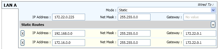
End-point device routing allows a device on one subnet to communicate with a device on separate subnet. There are two methods used to accomplish this task - a static route or the default gateway. A static route defines a specific destination/mask pair. The default gateway is a “catchall” for everything which doesn’t match a static route. Below is an example of a static routing configuration using Q-SYS Configurator in Q-SYS Designer.
For Q-SYS to work across a layer-3 network, the network must be configured to route the multicast addresses used by clock distribution and discovery protocols. Q-SYS devices implement the Internet Group Management Protocol (IGMP). IGMP allows network devices to register to receive specific multicast addresses. You can meet Q-SYS multicast routing requirements most easily on a layer-3 network with network equipment supporting IGMP and configured to enable multicast routing. Security policy may require tightening of multicast routing service around Q-SYS requirements. The following IP multicast addresses are used by Q-SYS.
For a list of Qualified and Unqualified Switches, refer to the Ethernet Switches topic.
Switches used with a Q-SYS system must meet the following minimum requirements:
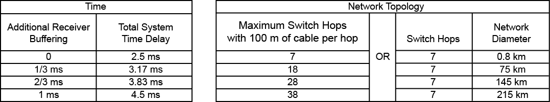
NOTE: To measure the network diameter, measure between the two nodes with the longest physical path in the network.
The following are general examples of networks meeting the network topology requirements. Other configurations are possible and would have different requirements based on the individual configuration.
Designers are free to use 10 Gigabit in place of 1 Gigabit while following the 1 Gigabit design rules.
Hop count is defined as how many switches there are between two system nodes.
Since all Q-SYS equipment is 1000BASE-T, the diameter of a 1-hop network is limited to 200 meters by the two 100 meter 1000BASE-T CAT-5e cables leading into the single Ethernet switch in a 1-hop scenario.
The maximum allowed diameter for a 2-hop network is 35 kilometers.
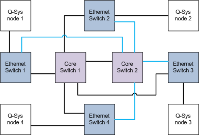
NOTE: The Q-SYS central processor is referred to as a Core. In this topic, "core" refers to the core switch in a network.
The longest path in this 3-hop core-switch configuration, for example, "Q-SYS node 1" -to- "Ethernet Switch 1" -to- "Core Switch" -to- "Ethernet Switch 2" -to- "Q-SYS node 2", can be no longer than 29 kilometers.
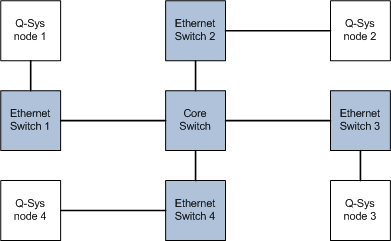
The longest path in this 4-hop core-switch configuration, for example, "Q-SYS node 1" -to- "Ethernet Switch 1" -to- "Core Switch 1" -to- "Core Switch 2" -to- "Ethernet Switch 2" -to- "Q-SYS node 2", can be no longer than 22 kilometers.
The maximum allowed diameter for a 5-hop network is 15 kilometers.
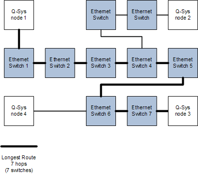
The maximum allowed diameter for a 6-hop network is 7 kilometers.
In the illustration below, between "Q-SYS node 1" to "Q-SYS node 3", there are 7 switches or hops. None of the cables in this configuration can be longer than 100 meters.
The Core has the following capacity constraints:
NOTE: You can check your design for these parameters by selecting File > Check Design... or by pressing Shift-F6.
The following information is for a Core 4000.
Since all channels pass through the Core, Core capacity limits system size in terms of channel count and ultimately device count.
Each Core has two network connections. Network redundancy duplicates output data on the second port so one Core may transmit up to 1024 channels in up to 256 streams. The Core receives 512 channels in up to 128 streams from elsewhere on the network. In addition, you can transmit these channels redundantly on two network interfaces. Therefore, up to 2048 channels in up to 512 streams may be present on the network during operation.
The Core can receive each individual stream input from a unique redundant pair of devices. The Core can direct each pair of stream outputs to a unique redundant pair of devices. The absolute largest number of audio devices populating a network is therefore ( 128 input streams * 2 redundant pair input devices ) + ( 128 output stream pairs * 2 redundant pair output devices ) + 2 Cores = 514 devices.
© 2009 - 2016 QSC, LLC. All rights reserved. QSC and the QSC logo are trademarks of QSC, LLC in the U.S. Patent and Trademark office and other countries. All other trademarks are the property of their respective owners.
http://patents.qsc.com.
![]()
 Related Topics